On this page
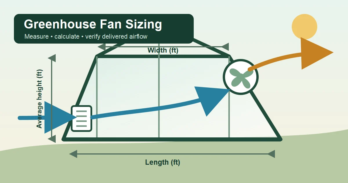
For a summer exhaust-fan starting point, UMass Extension uses 8 CFM per square foot of floor area for an average-size greenhouse. UMass Extension identifies this reference and its conditions. Treat that as a source-specific design reference, not a universal rule. Measure inside length, width, and average height; calculate target airflow; then check intake area and current fan performance at system static pressure. The result is a planning estimate, not a guarantee of temperature, humidity, or condensation control. See the broader greenhouse ventilation guide for system context.
Start with exhaust airflow, not circulation airflow
An exhaust fan moves greenhouse air out and draws replacement air through an intentional intake path. A circulation fan moves air within the greenhouse. They solve different problems, so do not add circulation-fan ratings to the exhaust target or use a circulation fan as the exhaust calculation.
Greenhouse fan-sizing worksheet
Record inside dimensions. Use average inside height when the roof profile changes; for a non-rectangular greenhouse, rectangular volume is an approximation.
| Input or result | Symbol | Calculation | Use |
|---|---|---|---|
| Inside length | L | _____ ft | Measure inside |
| Inside width | W | _____ ft | Measure inside |
| Average inside height | Havg | _____ ft | Estimate average height |
| Floor area | A | L × W = _____ ft² | Basis for UMass reference |
| Approximate volume | V | L × W × Havg = _____ ft³ | Needed for ACH conversion |
| Reference exhaust airflow | Qref | 8 × A = _____ CFM | Source-specific summer estimate |
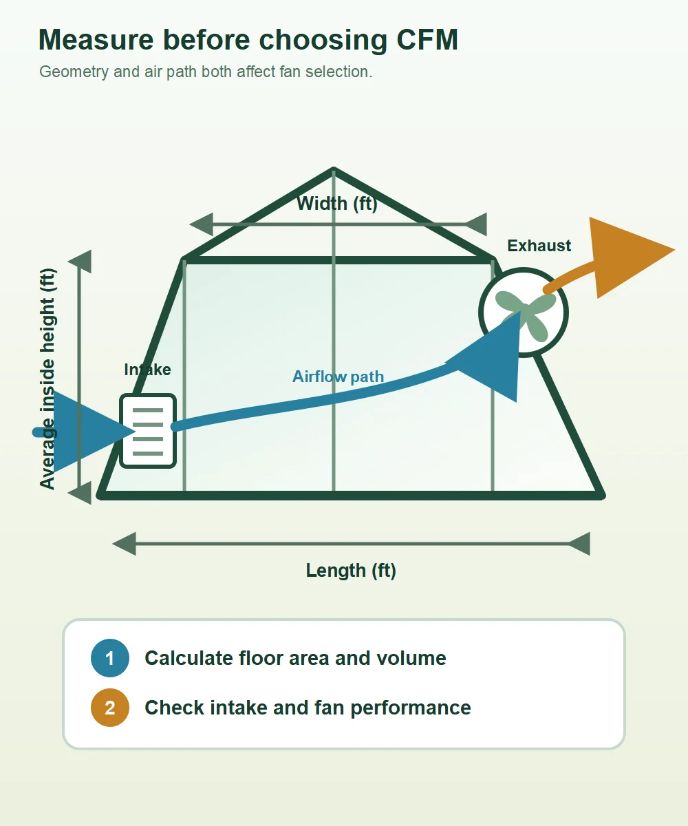
UMass Extension gives the 8 CFM/ft² reference for an average-size greenhouse. Its summer ventilation need also varies with greenhouse height, weather, solar radiation, outdoor temperature, and tightness. Apply the reference with those limits visible; do not label the result as the correct size for every greenhouse. UMass Extension explains the reference and its conditions.
Calculate equivalent air changes per hour
Use ACH to describe an airflow result after choosing a declared CFM basis:
ACH = CFM × 60 ÷ volume
This is a unit conversion, not a standalone design rule. If a separate source gives an ACH target, convert it with CFM = volume × ACH ÷ 60. Do not choose an unsupported ACH value and present the resulting CFM as a validated fan size.
Why 8 CFM/ft² can equal 60 ACH
UMass describes an average 8-foot greenhouse as receiving about one air change per minute at its reference rate. The arithmetic is 8 CFM/ft² × 60 minutes/hour ÷ 8 ft = 60 ACH. That equivalence depends on the 8-foot average height. A taller or shorter greenhouse produces a different ACH for the same floor-area airflow, so 60 ACH is not a universal greenhouse target.
Worked example: 12 × 8 × 8 feet
Hypothetical rectangular greenhouse:
- Floor area:
A = 12 ft × 8 ft = 96 ft². - UMass reference airflow:
Qref = 8 CFM/ft² × 96 ft² = 768 CFM. - Approximate volume:
V = 12 ft × 8 ft × 8 ft = 768 ft³. - Equivalent air changes:
ACH = 768 CFM × 60 ÷ 768 ft³ = 60 ACH.
The 12 × 8 × 8 dimensions are hypothetical inputs. The 96 ft² and 768 ft³ results are derived arithmetic. The 768 CFM value is the UMass reference applied to this example, not a product performance claim or cooling guarantee.
Check intake area and airflow path
Exhaust airflow depends on replacement air reaching the fan. UMass Extension uses an inlet-area minimum of 1.25 times the fan area as a check. Treat that as a minimum reference, not a guarantee. Screens, louvers, shutters, bends, and other restrictions can add pressure loss and reduce delivered airflow. UMass Extension documents the intake-area check and restriction concern.
- Identify the fan opening area used for the intake-area comparison.
- Check whether screens, shutters, or louvers narrow the free opening.
- Inspect the full path for avoidable restrictions.
- Keep the intake check separate from the exhaust CFM calculation.
Compare fan data at static pressure
Do not treat a free-air listing as delivered greenhouse airflow. Before selecting equipment, use current manufacturer or certified performance data for the exact fan at the expected system static pressure. Compare the fan performance at the pressure your intake, screens, shutters, louvers, and duct or path restrictions are expected to create. Then use the fit-first exhaust fan guide to compare exact models against those defined inputs.
- Match the fan-table airflow to the
Qrefplanning estimate. - Read the performance value at the relevant static-pressure point.
- Account for the intake path rather than comparing free-air numbers alone.
- Recheck current documentation before purchase because models and performance data change.
Limits before treating the estimate as a decision
Stop and get more specific guidance when climate, solar load, greenhouse height, tightness, humidity goals, equipment location, electrical requirements, clearance, or structural work could change the decision. This guide does not calculate heat load, predict relative humidity or condensation, select a wet-location device, specify wiring or mounting, or approve roof and wall modifications. Check current model instructions, equipment markings/listing, and local requirements; use qualified help when uncertain.
Use the worksheet to create a transparent starting estimate, then verify intake restrictions and exact fan-table performance at static pressure. If those inputs cannot be verified, the CFM number is not enough to support a purchase decision. If you are evaluating a solar-powered fan after airflow and operating watts are known, use this solar greenhouse fan planning guide to check the decision sequence, then continue to the solar greenhouse fan calculator to screen panel energy and optional reserve separately.