On this page
Place your primary greenhouse temperature sensor near the plant canopy in a representative zone, shield it from direct sun, and keep it out of direct heater, fan, vent, and intake streams. Then compare it with a suitable nearby reference under the conditions that normally cause trouble. The goal is not one universal mounting distance. The goal is a reading that represents the air your plants and controls are meant to respond to.
This guide covers air-temperature sensor location and verification. It does not set crop temperatures, certify calibration, prescribe controller wiring, select products, or measure leaf, root-zone, media, or surface temperature.
Start with plant-level air, not an easy-to-reach wall
Put the primary sensor where the controlled air matters: near the height and area of the plants or work zone it represents. UF/IFAS maintenance guidance recommends placing thermostats at or near crop level, while UAF Cooperative Extension describes plant-canopy height as the relevant control location. Neither source establishes one distance that fits every greenhouse.
“Near the plants” does not mean touching leaves, sitting above a wet tray, or hiding inside a dense pocket. Choose a location with air that mixes with the zone you want to manage. If benches, curtains, shelves, or a changing canopy divide the structure, one convenient sensor may not represent every zone.
Remove radiation and equipment bias
Temperature sensors can read a local object or air stream instead of the surrounding greenhouse air. Shield the sensing element from direct sunlight and strong radiant surfaces while leaving airflow around it. UF/IFAS temperature-sensor guidance, UAF Extension, and UF/IFAS cold-protection guidance support shielding without supplying a universal clearance.
| Distortion source | Why reading can mislead | Placement response | Verification clue |
|---|---|---|---|
| Direct sun or hot glazing | Radiation can warm the sensor or shield above surrounding air | Move into shade while retaining free airflow | Reading changes sharply with shade or sun angle |
| Heater discharge | Sensor sees a local warm plume before the zone warms | Keep outside the direct discharge path | Reading tracks heater cycles more than nearby air |
| Fan outlet or intake/vent stream | Forced or outside air may not represent occupied-zone air | Move out of the direct stream; compare during equipment states | Difference appears only when fan, vent, or intake operates |
| Outside wall, door, or cold frame | Surface and draft effects create an edge microclimate | Use a representative interior zone unless edge risk is the question | Reference disagrees mainly during wind or night cooling |
| Dense canopy, wet surface, or obstruction | Local humidity and airflow differ from general-zone conditions | Keep sensor exposed to representative moving air | Reading changes after watering, growth, or obstruction removal |
These are patterns, not fixed installation distances. A shield should block radiation without becoming a sealed enclosure. A fan can improve sampling when the design supports aspiration, but a fan outlet pointed at an unaspirated sensor can create a different local bias.
Prefer aspiration or clear, representative airflow
Aspirated sensing moves air across the sensing element so the reading responds to air temperature instead of slowly equilibrating with a nearby surface. UF/IFAS, UMass Amherst, Rutgers, and Virginia Cooperative Extension describe aspiration or airflow across the sensor as useful for representative greenhouse control.
Aspiration improves the sample; it does not prove calibration, accuracy, or correct placement. Keep the airflow path clean and follow the exact sensing-system documentation. Do not add wiring, modify a controller, or move a safety control based on this article alone.
Decide whether one sensor is enough
Use one primary control sensor only when one location reasonably represents the zone being controlled. Investigate more than one point when the greenhouse has separate bays, different bench heights, strong sun-and-shade differences, a cold perimeter, curtains, dense canopy, or equipment that creates persistent gradients.
First map the pattern: when does the difference occur, where is it, and which equipment or weather state is active? UF/IFAS cold-protection guidance recommends checking known cold spots when temperatures are not uniform. That can show whether another monitoring point is useful, but it does not create a universal sensor-count rule.
- One representative zone: use one control sensor and document its location.
- Known edge or pocket: add a diagnostic reading before changing a setpoint or equipment.
- Persistent multi-zone difference: follow controller and equipment documentation for any multi-sensor control decision.
- Safety-critical disagreement: stop and obtain exact manufacturer or qualified support rather than guessing which sensor is correct.
Verify placement with paired readings
A paired-reading check compares the control sensor with a suitable reference at the same time, in the same unit, while recording sun, wind, doors, vents, fans, heaters, shade, and canopy conditions. UAF and UMass guidance both describe comparing a thermometer near the thermostat or control sensor. This is a diagnostic check, not a calibration certificate: location, response time, shielding, aspiration, and instrument accuracy can all contribute to disagreement.
- Record the control sensor location and the condition being investigated.
- Place the reference nearby without putting either instrument in direct sun, discharge air, or contact with a hot or cold surface.
- Record both readings at the same time and in the same unit.
- Repeat during a meaningful contrast, such as heater off/on, sunny/cloudy, fan off/on, or day/night, without changing several variables at once.
- If the difference follows one location or equipment state, correct the sampling problem before changing a setpoint.
- If disagreement persists, follow exact instrument documentation or seek qualified support.
For the broader measure–act–verify loop, use the greenhouse temperature control guide. For temperature and relative-humidity interaction, use the greenhouse humidity control guide. If the question is stagnant air rather than outside-air exchange, use the greenhouse air circulation guide.
Use this placement worksheet
Complete one field sheet per sensor and investigation before changing a thermostat target or adding equipment. Leave unknown fields blank rather than inventing precision. Use the accessible worksheet below, print it from the browser, or download the full-size Sensor Placement Field Sheet.
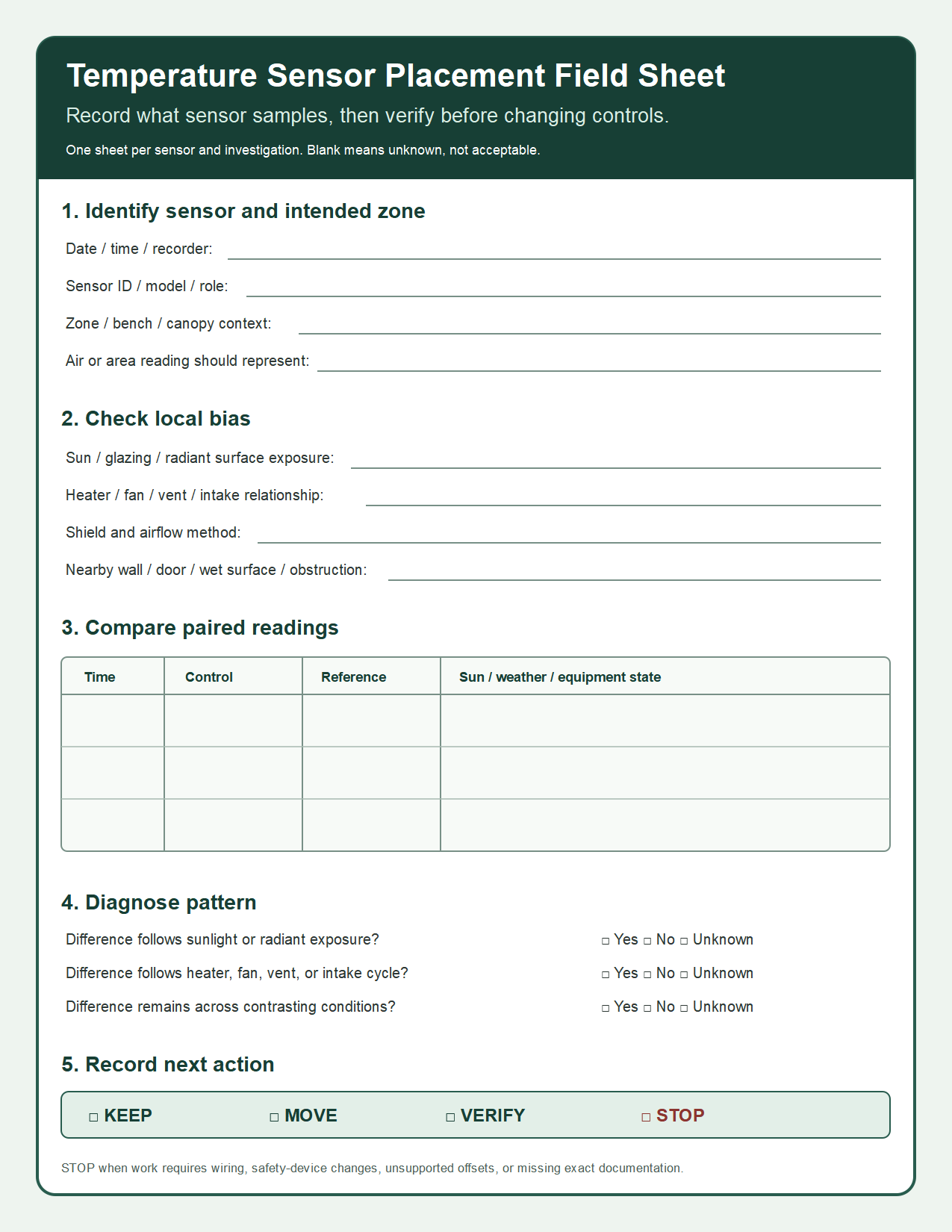
| Field | Record | Why it matters |
|---|---|---|
| Sensor ID and control job | ________________ | Separates control, display, alarm, and diagnostic roles |
| Zone, bench, and canopy context | ________________ | Shows what air the reading should represent |
| Sun/radiant exposure | ________________ | Identifies radiation or hot-surface bias |
| Heater/fan/vent/intake relationship | ________________ | Identifies discharge, draft, or outside-air influence |
| Shield and airflow method | ________________ | Records whether radiation is blocked and air reaches the sensor |
| Reference and paired difference | ________________ | Documents verification, not a calibration claim |
| Weather/equipment state | ________________ | Makes repeated checks comparable |
| Next action and stop condition | ________________ | Prevents disagreement from becoming unsafe work |
Follow the placement decision tree
- Reading looks wrong: compare it with a suitable nearby reference under the same conditions.
- Difference follows sunlight: correct radiation exposure while preserving representative airflow, then repeat the comparison.
- Difference follows an equipment cycle: move the sensor out of the direct heater, fan, vent, or intake stream, then repeat the comparison.
- Difference remains across contrasting states: verify instrument documentation or monitor another representative zone before changing control settings.
- Decision requires unsupported offsets, wiring, or safety-device changes: choose STOP and obtain exact manufacturer or qualified support.
Record one outcome: KEEP when placement remains representative; MOVE when location bias is identified; VERIFY when evidence remains incomplete; or STOP when safe action requires documentation or qualified support.
Review the record when canopy, shade, curtains, benches, airflow path, heater, fan, vent, or control equipment changes. An old placement record is not proof that a changed greenhouse still has a representative sample.
Stop before unsupported or unsafe changes
- The decision depends on a crop-specific temperature, alarm, or night target not established here.
- A thermostat, controller, safety device, mains circuit, heater, fuel system, combustion appliance, or wiring must be moved, bypassed, or modified.
- Two instruments disagree and no suitable reference, documentation, or qualified support is available.
- The sensor is being used to infer leaf, root-zone, media, surface, or disease conditions that air temperature cannot establish.
- A proposed correction requires an invented offset, universal distance, or guaranteed accuracy claim.
Good placement makes a control decision more representative; it does not remove uncertainty. Sample the air that matters, remove obvious local bias, verify under meaningful conditions, and keep equipment-specific safety decisions inside exact documentation.
Sources and methodology
This article synthesizes university Extension and controlled-environment guidance into a placement matrix and worksheet. No original greenhouse measurement, installation, calibration test, product test, crop trial, or owner case supports the recommendations.