On this page
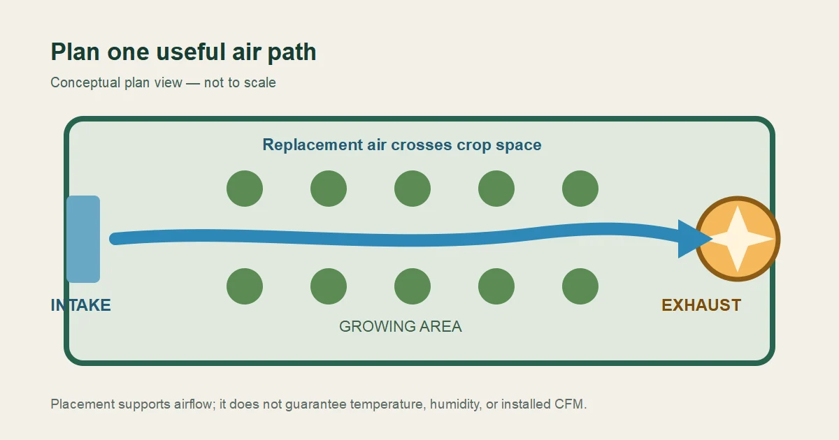
Place a greenhouse exhaust fan and its replacement-air intake as one system: commonly, the fan sits in one end wall and the planned intake openings sit at the opposite end so incoming air crosses the growing area. That is a planning pattern, not a universal rule. Before choosing a wall, sketch every opening, obstruction, and crop or bench zone, then trace the shortest likely route from intake to exhaust.
This guide covers physical airflow paths. It does not size a fan, specify a wall cutout, or provide electrical or structural installation instructions. For whole-system context, see the greenhouse ventilation guide. For CFM and fan-data checks, use the greenhouse fan sizing guide and its greenhouse ventilation calculator.
Plan exhaust and intake as one path
An exhaust fan only pulls air from where replacement air can enter. A common end-wall arrangement places the exhaust fan at one end and intake louvers or other planned openings at the opposite end, where the structure allows it. Extension guidance describes this as a way to move air through the crop space rather than relying on a nearby opening. UMass Amherst Extension explains greenhouse ventilation layouts, and Farm Energy describes the opposing fan-and-louver arrangement.
- Start with the occupied zone. Draw the benches, tall plants, shelving, and other features that air must cross.
- Mark both endpoints. Identify the proposed exhaust location and every realistic replacement-air opening.
- Trace routes. Prefer a useful path through the growing area, not a short route from a door, crack, or opening beside the fan.
- Check restrictions. Note screens, shutters, louvers, vegetation, stored materials, and exterior walls or fences near either endpoint.
“Opposite” does not mean maximizing distance at any cost. It means creating the longest practical useful path through occupied greenhouse space while respecting the building, equipment instructions, and site conditions.
Seven-point placement walk-through
1. Draw the greenhouse in plan view
Use a simple top-down sketch. Include end walls, sidewalls, doors, vents, screens, benches, dense crop areas, and any opening that could admit air. This exposes shortcut paths before equipment is mounted.
2. Choose the intended cross-house direction
For a compact house, an end-wall exhaust with intake at the opposite end is often the clearest starting layout. Keep the intended path through the growing area. Oklahoma State Extension also describes cross-flow with the inlet opposite the exhaust and notes that low intake with higher exhaust can support warm-air removal; that does not establish a universal mounting height or guarantee.
3. Look for the shortest competing opening
A door or vent beside the exhaust can become the easiest route when open. Treat this as a layout diagnosis, not a measured performance claim. If the sketch shows most replacement air entering near the fan, move the planned intake path or control the competing opening according to the actual greenhouse design. If placement is only one possible cause, use the ventilation failure trace before changing equipment.
4. Keep the draw within source guidance
UMass Amherst Extension and Farm Energy advise keeping the fan draw below 150 feet. They describe longer houses as candidates for a sidewall arrangement or other system-specific design. Treat this as source-specific extension guidance, not a code limit and not proof that every shorter greenhouse needs one particular layout.
5. Check the crop-zone path
Trace air over or through the canopy and around benches. A large plant mass, solid shelving, or stored material can redirect the path. The goal is not to promise uniform temperature or humidity; it is to avoid placing both endpoints so that air bypasses the space you are trying to ventilate.
6. Inspect wind and outside obstructions
Check prevailing summer wind at the proposed exhaust side. UMass guidance notes that wind can affect discharge and that exhausting against opposing wind can reduce fan output. Use wind as a site check, not as an “always place the fan downwind” rule. Also look for vegetation, walls, screens, or stored items that obstruct intake or discharge.
7. Recheck the opening and equipment boundary
Intake louvers, shutters, screens, and discharge openings must fit the exact equipment and greenhouse conditions. Restrictions can reduce delivered airflow, but the amount cannot be inferred from a generic placement sketch. Free-air CFM also does not verify installed airflow under system pressure; use exact fan data and the sizing guidance before selecting equipment. Once placement and path constraints are defined, compare greenhouse exhaust fans by documented fit.
Bad shortcut versus intended cross-house path
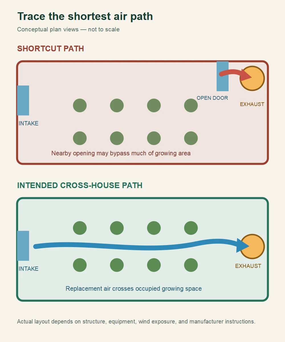
In the bad-shortcut example, replacement air can enter beside the exhaust, so the fan may pull mainly from that nearby opening. In the intended cross-house example, the planned intake sits across the growing area. The diagram shows a planning distinction, not a measured comparison or performance guarantee.
Placement decision table
| Layout condition | Planning direction | What to verify |
|---|---|---|
| Short, clear greenhouse | Start with exhaust at one end and planned intake at the opposite end. | Air path crosses the occupied growing area. |
| Long structure | Do not stretch an end-to-end plan automatically; investigate a sidewall or other system-specific arrangement. | Source guidance keeps draw below 150 ft; longer layouts need closer review. |
| Door or opening beside exhaust | Identify it as a competing shortcut and trace what happens when it is open. | Whether replacement air still enters from the intended location. |
| Prevailing summer wind at exhaust side | Use wind direction to assess discharge conditions, not to impose a universal wall rule. | Whether opposing wind or nearby obstructions may hinder discharge. |
| Restricted intake | Keep screens, shutters, louvers, and vegetation in the airflow review. | Exact opening and fan data; generic nominal area is not proof. |
| Blocked exterior discharge | Resolve the obstruction in the design review before relying on the fan location. | Exact fan instructions and site-specific discharge conditions. |
| Benches or dense crop zone | Trace air over or through the canopy instead of around the occupied space. | Whether solid items create a bypass or blocked route. |
Use the table to compare layouts, not to assign a score. The better location is the one that gives replacement air a practical route through the growing area with fewer restrictions and fewer nearby shortcuts.
Exhaust fan versus circulation fan
A circulation or horizontal-airflow fan mixes air already inside the greenhouse. It can help move air around the crop zone, but it does not replace a planned outside-air intake and exhaust path. Keep those jobs separate when diagnosing weak ventilation: first inspect the replacement-air route, then consider internal circulation. For symptom-based diagnosis, use the greenhouse circulation fan versus exhaust fan guide.
When to stop planning and get review
Stop at the sketch when the next step would require changing the structure or connecting equipment. Wall cutting, framing changes, electrical work, clearances, and local requirements depend on the exact greenhouse, fan, manual, and jurisdiction. Follow manufacturer instructions and use qualified help where required. This article does not tell you how to cut a wall, wire a fan, or establish a wet-location or code requirement.
Also pause when the proposed layout has unresolved model or variant identity, conflicting dimensions, blocked discharge, or a route that cannot be traced through the crop zone. Those are design-review problems, not details to fill with a generic rule.
Placement checklist
- Sketch greenhouse in plan view.
- Mark exhaust, planned intake, doors, vents, screens, benches, crops, and obstructions.
- Trace shortest intake-to-exhaust route.
- Prefer practical cross-house flow through growing area where structure allows.
- Check draw against source guidance; longer houses may need sidewall planning.
- Review prevailing summer wind and exterior discharge obstructions.
- Stop before structural or electrical work; verify exact equipment and qualified requirements.
Bottom line: choose fan and intake locations together. A common end-wall cross-flow layout works as a planning starting point when it creates a useful path through the greenhouse, but the actual structure, openings, wind, restrictions, and equipment instructions decide whether it fits.
Sources and methodology
This planning guide synthesizes extension guidance and fan-rating standards. Sources describe common airflow arrangements and system limitations; they do not establish a universal mounting location, installed CFM, cooling result, humidity result, or clearance for every hobby greenhouse.