On this page
For a mechanically exhausted greenhouse, start with UMass Amherst Extension’s minimum screening reference: inlet area at least 1.25 × fan area. That is only a starting screen. UMass does not define which fan-area or inlet-area measurement basis controls, so do not treat blade diameter, housing size, flange size, a retailer photo, or a rough cutout as the answer. Confirm the exact basis in current equipment documents, then check free area, pressure-drop data, screens, shutters, and the operating stage you plan to run.
This guide owns intake-opening sizing and intake-assembly evidence. Its calculator screens documented fan-area and candidate-inlet inputs; it does not size greenhouse CFM demand, choose opening locations, provide wall-cutting or wiring instructions, or establish code compliance. For whole-system context, read the greenhouse ventilation guide. For fan demand and fan-data interpretation, use the greenhouse fan sizing guide and greenhouse ventilation calculator.
AREA SCREEN · NOT AIRFLOW PROOF
Intake vent screening calculator
Use an exact, documented fan-area basis. Full precision stays in calculation; displayed values are rounded.
Minimum target1.25 × total stated fan area
Total stated fan area—in²
Minimum target—in²
Target converted—ft²
Candidate area compared——
Published free area: —
Passing this area screen does not prove delivered CFM, acceptable pressure drop, code compliance, or installed performance.
Calculation record
What greenhouse intake vent size means
An intake assembly is more than a hole in a wall. It can include a louver, shutter, screen, weatherhood, frame, damper, or other restriction between outside air and the exhaust fan. Each component can change the opening that air actually passes through. UMass describes inlet louvers and fans as parts of one ventilation system, and Farm Energy also treats inlets, fans, and airflow paths as a connected system. Before changing vent area, use the ventilation troubleshooting guide to rule out a stuck opening, obstruction, control call, path shortcut, or outdoor-load limit.
That distinction creates two separate questions:
- Area screen: Is the documented inlet-area basis at least 1.25 times the documented fan-area basis for the operating stage?
- Assembly review: What free-area, pressure-drop, component-state, and restriction evidence shows whether the selected assembly can support the intended system?
A pass on the first question is not a measured airflow result. It does not establish delivered CFM, acceptable pressure drop, or compliance with a building or electrical requirement.
Identify exact inputs before calculating
Collect documents for the exact fan, louver, shutter, screen, and weatherhood configuration you are considering. Record the model or part identity and market when available. Then identify the area basis each document actually defines.
- Fan-area basis: documented opening, catalog area, or another explicitly defined dimension.
- Inlet-area basis: documented nominal face area, opening area, or another explicitly defined basis.
- Component state: open, closed, partially open, powered, gravity-operated, screened, or otherwise restricted.
- Published free area: candidate-specific value or table, not a guessed percentage.
- Pressure evidence: pressure drop or rated performance data at a relevant airflow and test condition.
- Operating stage: which fans and restrictions are active together.
If a document does not define the relevant area basis, mark it unknown. Do not fill the gap with a familiar dimension.
Apply the 1.25× minimum screening reference
UMass Amherst Extension states that air-inlet louver area should be at least 1 1/4 times fan area. Use that as a minimum screening reference, not as a universal free-area rule or a guarantee of installed performance. The source does not define whether “fan area” means blade diameter, housing opening, flange, or another catalog dimension, and it does not define the inlet-area basis for every louver design. Read UMass Amherst Extension’s ventilation guidance before applying the screen.
Use only dimensions that the exact equipment documentation identifies as relevant. For defined geometric openings:
- Round opening area =
π × diameter² ÷ 4. - Rectangular opening area =
width × height. - Screening target =
1.25 × documented fan-area basis.
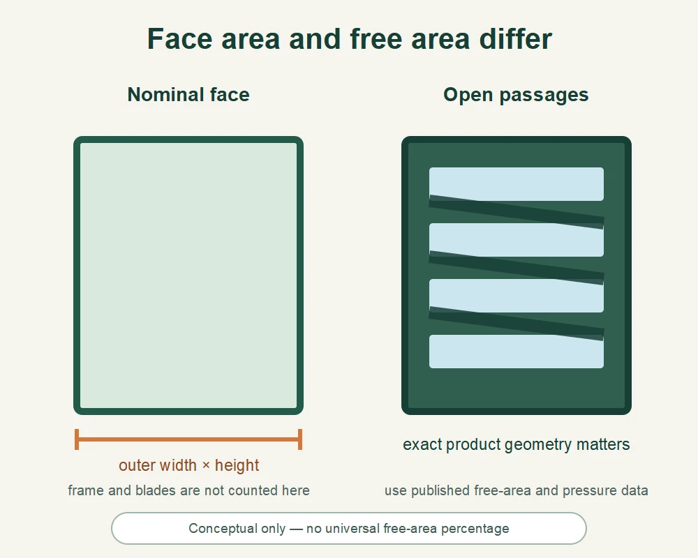
These formulas calculate geometric area only. They do not convert nominal area into free area, and they do not predict pressure drop or installed airflow.
Worked example: two fans in one operating stage
Suppose equipment documentation explicitly defines two relevant rectangular fan openings, each 24 × 24 in. This is a hypothetical calculation example, not a measured installation:
- Area for one documented opening:
24 × 24 = 576 in². - Total area for two fans running together:
2 × 576 = 1,152 in². - Minimum screening reference:
1.25 × 1,152 = 1,440 in². - Convert the geometric result:
1,440 ÷ 144 = 10.0 ft².
The result is a 10.0 ft² minimum screen on that stated basis. It does not mean a nominal 10.0 ft² louver provides 10.0 ft² of free area or will pass the required airflow at acceptable pressure drop. If the exact fan-area basis is not defined, stop instead of calculating from blade, housing, flange, or photo dimensions.
Use the Intake Assembly Evidence Worksheet
Use this worksheet to separate what is known from what still needs product-document review. A useful result is not always a number. It may be minimum screen only, product-data review needed, or stop—basis unknown.
| Worksheet field | Record | Why it matters |
|---|---|---|
| Exact fan identity | Model, variant, market, document date | Prevents mixing dimensions from different equipment. |
| Fan-area basis | Defined dimension and source passage | Controls whether the 1.25× screen is reproducible. |
| Operating stage | Fans, shutters, screens, and dampers active together | Area must match the stage being checked. |
| Each intake component | Louver, shutter, screen, weatherhood, frame | Restrictions belong to the assembly, not only the outer opening. |
| Nominal face area | Width × height or documented basis | Describes outer geometry; does not prove free area. |
| Published free area | Exact candidate value and test context | Supports comparison without guessing a percentage. |
| Pressure evidence | Pressure drop, airflow, and rated condition | Free area alone does not establish system performance. |
| Unknowns | Missing definition, state, rating, or obstruction | Turns uncertainty into a stop or review decision. |
Greenheck’s louver guidance distinguishes face area, free area, airflow, pressure drop, and water-penetration considerations. AMCA Publication 511 describes rated louver performance under defined test methods. Use those sources to interpret candidate data, not to substitute certification or a free-area number for installed verification. Review Greenheck’s louver fundamentals and AMCA Publication 511.
Check staged fan operation
Do not calculate one opening target from a fan that runs alone if two or more fans can run together. Check each intended operating stage and sum the documented fan-area bases for fans operating in that stage. The stage assumption is an editorial application of the inlet-and-fan system principle; it is not a new universal sizing formula. Farm Energy’s greenhouse ventilation guidance provides system context for matching inlets and fans.
- Single-fan stage: check the fan and restrictions active during that stage.
- Combined stage: sum the documented bases for fans expected to run together.
- Changed component state: recheck when a shutter, screen, damper, or louver changes state.
- Unknown sequence: stop until controls and component states are documented.
Treat free area and pressure as separate checks
Nominal face area is the outside face dimension. Free area is the portion left open after frame and blade restrictions. A large face can still have limited open passage, while a published free-area value still does not tell you the complete system result.
UF/IFAS explains that fan output depends on system resistance and static pressure. Greenheck connects free area with airflow and pressure-drop selection. AMCA’s rating framework defines test conditions for comparable louver data. Together, these sources support a narrow conclusion: free area helps screen candidates, but free area alone does not establish delivered CFM or installed performance. Read UF/IFAS greenhouse ventilation guidance.
Find restrictions before blaming the fan
UMass, Farm Energy, and UF/IFAS describe restrictions and system resistance as performance concerns. Check the complete intake path for:
- Closed or partly open motorized shutters.
- Clogged, wet, damaged, or incorrectly fitted screens.
- Debris, leaves, crop growth, stored material, or other blocked passages.
- Extra frames, weatherhoods, dampers, or louvers omitted from the first calculation.
- A component document that reports a different state or test condition than the planned use.
These checks identify possible restrictions; they do not quantify a loss percentage. If airflow seems inadequate, compare the actual component state and available documentation before changing equipment. After intake evidence is resolved, use the exhaust fan buying guide to compare compatible exact models.
Stop before buying or modifying anything when
- The exact fan or louver identity is unresolved.
- The documentation does not define the area basis used in the calculation.
- A catalog, retailer, or photograph gives dimensions without stating what they measure.
- Free-area or pressure data is missing where the candidate comparison depends on it.
- Fans can stage together but controls or component states are unknown.
- The proposed work changes structure or electrical equipment.
Do not cut an opening, alter framing, modify wiring, or assume a wet-location or clearance requirement from this article. Follow current manufacturer instructions and obtain qualified help where the work requires it.
Action summary
- Identify exact fan and intake-component documents.
- Record the defined fan-area and inlet-area bases.
- Apply UMass’s
1.25×figure as a minimum screening reference only. - Check each operating stage and every restriction in the assembly.
- Compare published free-area and pressure-drop evidence for the exact candidate.
- Stop when identity, basis, state, or safety boundary remains unresolved.
Sources and methodology
This research-based guide uses UMass Amherst Extension, Farm Energy, UF/IFAS Extension, Greenheck technical documentation, and AMCA Publication 511. The worked example uses stated hypothetical dimensions to show arithmetic. No original installation, airflow measurement, product test, or field observation supports this article.
- UMass Amherst Extension: Ventilation for Greenhouses
- Farm Energy: Greenhouse Ventilation
- UF/IFAS Extension: Greenhouse Ventilation
- Greenheck: Louver Fundamentals and Selection Considerations
- AMCA Publication 511-21 (Rev. 12-22)
For the next decision, use the greenhouse exhaust fan placement guide for airflow-path planning. This page remains a bounded screening and evidence guide, not a construction, electrical, code, or performance guarantee.